
Open up a wireless charging pad and the part that decides whether it feels good is rarely the controller chip. It is the copper. A coil is an inductor first: inductance sets the resonant point, and AC resistance decides how much of the power budget turns into heat. Around that, the industry really only has two mainstream process routes, and the difference is whether you print the copper or wind it.
Printing means PCB planar spirals and multi-layer flex coils. The advantages are on the label: the thinnest option, geometry defined photolithographically so coil-to-coil spread is small, and near-zero cost if the coil rides on a board you were already building. The catch is copper thickness, capped by the process at roughly 35µm for 1oz copper, where skin effect pushes effective resistance up and Q down. One frequently cited comparison puts a well-executed printed litz-style winding about 37% higher in Q than an equal-width, equal-spacing printed spiral at 150kHz, which means that with printed coils, layout matters more than the fab.
Why Wound Coils Still Hold the Mainstream
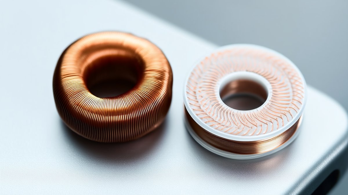
The WPC reference transmitter coil A11 is instructive: 17 AWG Type 2 litz, 105 strands of 40 AWG, a bundle about 1.15mm across, roughly 10 turns, about 50mm across, and near 6.3µH ±10% behind a ferrite shield. Nobody picks 105 strands for looks. A solid conductor of the same area would waste most of its copper to skin effect. Winding frees the conductor cross-section from any lamination process, so DC resistance is lower and Q is higher, which is why nearly every Qi reference coil is wound. The price is thickness: bundle diameter sets the floor, and winding tension and termination add variance.
Where Thin Wins Anyway
Wearables push the question to its limit. In a smart ring the coil assembly has to stay under 0.3mm: precision hot-air self-bonding winding lands at 0.18 to 0.28mm including shielding, multi-layer etched flex at 0.22 to 0.32mm, and laser direct structuring at 0.35 to 0.50mm. At equal thinness, wound designs typically measure Q of 35 to 55 against 20 to 35 for flex, a 30% to 50% gap. The ring's magnetic environment is brutal as well: a titanium shell and a metal battery soak up flux, eddy currents damp the coil, and Q can collapse from 40 to below 10, so a thin sintered ferrite shield of 50 to 80µm with permeability of 120 to 180 and a micro-cracked structure, so it still bends, is close to mandatory.
The short version: print when thinness and flexibility come first, wind when efficiency does. Multi-coil arrays and ultra-thin receivers are almost always printed; higher-power transmitters and car console panels are almost always wound. And when you talk to a supplier, do not stop at inductance. Ask for AC resistance, Q factor and the frequency at which Q was measured. If those three do not line up, the 25W on the box is just a number.
© SWPO. All rights reserved.